Detailed HVAC
In buildings, HVAC systems are comprised of components such as fans, pumps, coils, chillers and boilers connected by ducts or pipes and controlled by systems using sensors strategically located in the distribution systems and in the zones. In many respects, EnergyPlus mirrors this topology by having a large number of components and a means to describe their connections with one another and their control systems. Every component in an HVAC system must have an inlet and outlet "node." In the actual system, a node might be a point in the system at which fluid properties can be measured. In an EnergyPlus simulation, the nodes are points at which fluid properties are evaluated and passed on to subsequent equipment. Components are linked together to form various loops within the simulation. Thus, the output node from one component also serves as the inlet node to the next component. Loops are constructed combining the components as well as input objects the describe the arrangement of the components. The figure below shows a generic example of the loop-node concept. Loop nodes are a key defining feature in EnergyPlus. As a result, it is recommended that one of the first steps taken in defining an HVAC system in EnergyPlus be the definition of a node diagram or map. This is helpful for visualization of the entire system.
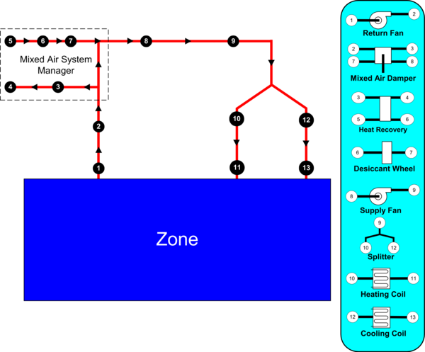
Example Node Diagram
So that these loops are manageable and more clearly defined both in the input and in the simulation, four different loop sections can be defined in an EnergyPlus input file. In general, these four types are in essence two pairs of loop sections that make up two distinct types of loops: a zone/air loop and a plant loop.
- Air Loop Supply Side: The air loop is defined by the section of the zone/air loop that starts after the zone return streams are combined and continues on until just before any air stream(s) are branched off to individual zones. The starting point of the air loop is fairly straightforward. The ending point is slightly more complex but can be understood with some examples. For instance, in a terminal reheat system, the end of the air loop would typically be considered the node following the cooling coil. In a dual duct system, the air loop would have two ending points that would correspond to the nodes after the cooling coil and after the heating coil/humidifier. In most cases, the air loop has a single starting point and up to two ending points (for a two-deck system). An outdoor air subsystem can be included in the supply side for ventilation and relief air.
- Air Loop Zone Equipment: The zone equipment section of the input file is defined as more or less the rest of the zone/air loop (outside air is handled separately as a subset of the air loop). This includes everything from where the ducts are split to serve various zones up through where the return ducts from various zones are mixed into a single return duct. Zone equipment can include dampers and reheat coils as well as zone-specific conditioning systems such as thermostatic baseboard or a window air conditioner. Most control issues are typically dealt with in the zone equipment section of the simulation.
- Plant Loop Demand Side: One side of the plant is where energy is "demanded" by various components that make up the air loop or zone equipment. Typically, this is the water side of equipment such as coils, baseboard, radiant heating and cooling, etc. In the case of a condenser loop, energy is typically "demanded" by a chiller condenser or other water source heat pump. The demand side of this loop can also include a splitter, a mixer, and a bypass.
- Plant Loop Supply Side: The other side of the plant loop is where energy is "supplied" by various components. The components typically found on the supply side include pumps, boilers, chillers, purchased heating and cooling, ice storage, etc. In the case of a condenser, the components would be a cooling tower, fluid cooler, or ground source heat exchanger, etc. As with the demand side, this loop can also include a splitter, a mixer, and a bypass.
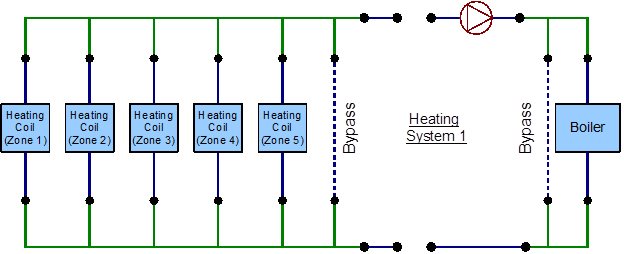
Detailed HVAC Heat Loop Line Diagram
The following is a list of groups of input objects related to specifying detailed HVAC systems in EnergyPlus related to zone equipment and secondary systems:
- HVAC Design Objects - describes input objects related to how EnergyPlus performs autosizing for air terminals, zone equipment, systems, and plant components as well as for outdoor air systems.
- Node-Branch Management - used to describe some of the topological features of EnergyPlus such as nodes, pipes, and ducts as well as branches (pieces of loops) and connectors.
- Air Distribution - describes the arrangement of the components in an air distribution system includes the outdoor air system, splitters, mixers, and plenums.
- Zone HVAC Controls and Thermostats - input objects related to thermostats and humidistats used to control the conditions in a zone.
- Zone HVAC Forced Air Units - defines input related to zone forced air equipment like window air conditioners, packaged terminal air conditions (PTAC), unit heaters, fan coil systems, and outdoor air units as well as other related input objects.
- Zone HVAC Radiative/Convective Units - models baseboard systems, low- and high-temperature radiant systems, and active portion of ventilated slabs.
- Zone HVAC Air Loop Terminal Units - describes air terminals including constant volume, variable volume, series and parallel powered induction units, and duel duct terminals.
- Zone HVAC Equipment Connections - used to describe the HVAC equipment connections at the zone level.
- Fans - describes constant volume, variable volume, exhaust fans as well as more system and component model fans.
- Coils - contains a long list of input objects to model heating and cooling water coils; heating and cooling DX coils including two-, multiple-, and variable-speed units; variable refrigerant coils; fuel and gas coils; desuperheater coils; air to water heat pump coils; and other coil input objects.
- Evaporative Coolers - describes direct and indirect evaporative coolers.
- Humidifiers and Dehumidifiers - for electric and gas steam humidifiers as well as desiccant dehumidifiers.
- Heat Recovery - models for air-to-air flat plate and combined sensible and latent heat exchangers as well as heat exchangers coupled with desiccants.
- Unitary Equipment - describes unitary input objects that are generally placed in the primary air loop and includes heating only, heating and cooling, and air-to-air heat pump input objects.
- Variable Refrigerant Flow Equipment - input objects to describe variable refrigerant flow (VRF) equipment as well as the controls.
The following is a list of control systems in EnergyPlus related to HVAC
- Controllers - input objects for simple controllers that look at a single node and compare it with the setpoint and includes controllers for water coils, outdoor air, and mechanical ventilation.
- System Availability Managers - these input objects can take an input from any node and control whether an entire portion of the HVAC system is active and can be based on temperature, differential temperature, schedules, night cycle, and ventilation.
- Setpoint Managers - these take input from any node or nodes and calculate a setpoint at another node and include controls for single zone heating, cooling, or reheat; humidity control; mixed air; warmest or coldest; and many other scenarios.
- Plant-Condenser Control - provides control for the plant loop primarily controlling the operation of the loop and which equipment is available and includes control based on heating or cooling load and in reference to outdoor conditions such as dry-bulb or wet-bulb temperature.
- Plant-Condenser Flow Control - describes the TemperingValve input object for the special case of flow control with thermal storage systems.
The following is a list of input objects related to primary systems and equipment:
- Pumps - describes constant speed and variable speed pumps and headered multiple pump systems.
- Plant-Condenser Loops - describes the supply and demand side of the loops the operating temperatures and flow rates.
- Plant Heating and Cooling Equipment - used to input the central plant equipment such as steam and hot water boilers; electric, absorption, engine driven, and turbine chillers; and water-to-water heat pumps; as well as connections to district heating and cooling sources.
- Condenser Equipment and Heat Exchangers - describes single-, two, and variable speed cooling towers; single and two speed evaporative and non-evaporative fluid coolers; vertical, surface, trench and slinky ground heat exchangers; and fluid-to-fluid heat exchangers.
- Non-Zone Equipment - describes the LoadProfile:Plant input object that allows the load on the plant to be specified by schedule if already known.
- User Defined HVAC and Plant Component Models - a group that allows the user to define custom models for zonal systems, air terminals, coils, and plant equipment.
The input object groups described in this section are further explained in the InputOutputReference.