Thermal Zones and Surfaces
The physical aspects of the building such as the walls, roof, and windows, is one of the most important and often challenging aspects of creating a building energy model. In EnergyPlus, the surfaces define the geometry of each zone and thus for the entire building. For many, a graphical user interface will be used to help define the geometric aspects of the building energy model, and many of the input objects described in this section will be directly created by that interface program. It is still important to understand some of the details for these input objects because it is likely that you will be reviewing them as part of debugging error messages. EnergyPlus uses the three dimensional position of each corner of a surface to define the position and orientation of that surface so for a typical rectangular wall that represents 12 numbers and for a typical building with hundreds of surfaces that means thousands of numbers are used to define the geometry of a building so you can see why using an interface is so common.
EnergyPlus uses a right-hand coordinate system as shown in Figure X with three dimensions. The X-axis points east, the Y-axis points north, and the Z-axis points up.
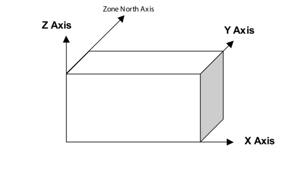
EnergyPlus Coordinate System
- Zone - defines the name of the thermal zone as well as the ceiling height, floor area, and volume. For most zones that are fully enclosed these three entries can be calculated automatically be EnergyPlus and do not need to be entered. A zone multiplier allows a single zone to represent many identical zones (such as all the enclosed offices on one side of a building). The name of the zone will be referenced in many places in the input file so it should be clear what it is describing. When defining a zone, it is important for the entire area to be thermally similar both in heat being transferred through exterior walls as well as interior heat gains. But using as few zones as possible (and thus as few surfaces) also can result in faster simulations, so there is no reason to slow down the simulation just so two (or more) essentially identical areas are each simulated. The coordinates can be just set to zero if the world coordinate system is used (see GlobalGeometryRules below).
- BuildingSurface:Detailed - lists the three-dimensional coordinates that define each corner as well as referencing the zone that the surface is attached to and the construction of the wall (list of materials). This input object supports any shape surface with three or more corners (vertices). In addition, this input object defines what is on the other side of the surface from the zone, whether that is outside, another zone in the building, or the ground. Other inputs indicate if the outside of the surface is exposed to the sun or the wind.
- FenestrationSurface:Detailed - describes windows, doors, and special daylighting tubes and it references the wall that it is part of. It also requires the specification of vertices (usually four but three is also allowed) to describe the corners of the window or door as well as the construction which, in this case, is generally the layers of glass and the gas fill between the layers. It has a field for a multiplier although usually the multiplier is set to one since the position of windows matters to many of the algorithms used. In order to describe the frame of the window and any dividers that it might have, a separate input object (WindowProperty:FrameAndDivider) may be included and referenced. A good example file is WindowsTests.idf. To understand how to model the many options for windows, a section and a table in the Input Output Reference called "Window Modeling Options" should be examined.
Shading Related
Casting shadows on the building, especially onto windows, can significantly impact the energy use of a building, and EnergyPlus includes several input objects to model this effect. The largest impact of shading surfaces is to reduce solar gain through windows that are shaded. There are two kinds of shading surfaces in EnergyPlus, detached and attached. A detached shading surface, such as a tree or neighboring building, is not connected to the building. An attached shading surface is typically an overhang or fin that is attached to a particular base surface of the building, usually a wall; attached shading surfaces are usually designed to shade specific windows.
- Shading:Site:Detailed - describes something near but not attached to the building that casts a shadow on the building such as nearby buildings or mountains and includes the vertex of one corner as well as the length and width. For deciduous trees, and other situations that shading changes over time, the schedule for the transmittance can vary, otherwise, it should always be set to zero or leave the schedule name blank.
- Shading:Zone:Detailed - describes an attachment to the building that casts a shadow such as an overhang or fin. It also includes a reference to a transmittance schedule. The wall that the fin or overhang is attached to is also specified.
If using relative coordinates (see GlobalGeometryRules), you may also want to use the Shading:Building:Detailed input object since it will "rotate" with the building. Typically, Shading:Site:Detailed is used for things that are fixed at the site and don't move with building rotation. Shading:Building:Detailed is for larger structures like a parking garage or canopy which aren't associated with a specific zone but would likely rotate with the building.
Input Object Variations
EnergyPlus includes a bunch of variations on these basic surface input objects that map to a closer representation of real surfaces in buildings. These input objects are effectively just different ways to represent the same information as the BuildingSurface:Detailed, FenestrationSurface:Detailed, and Shading:Zone:Detailed input objects. These input objects are seldom created by graphical user interfaces, so it is unlikely that you will see them. Some of these input objects also have simpler methods for specifying geometry, such as using a single vertex, height, width, tilt, and azimuth or just specifying the fin location relative to the window edge. The following is a list of these input object variations for surfaces:
- Wall:Detailed, Wall:Exterior, Wall:Adiabatic, Wall:Underground, Wall:Interzone
- RoofCeiling:Detailed, Roof
- Floor:Detailed, Floor:GroundContact, Floor:Adiabatic, Floor:Interzone
- Ceiling:Adiabatic, Ceiling:Interzone
- Window, Window:Interzone
- Door, GlazedDoor, Door:Interzone, GlazedDoor:Interzone
- Shading:Site, Shading:Building, Shading:Overhang, Shading:Overhang:Projection, Shading:Fin, Shading:Fin:Projection
Other Related Input Objects
- GlobalGeometryRules - A required input object that should be in all files. It sets the way geometry is specified for all of the surface input objects. The most common approach is that the order of coordinates for each surface should start with the upper left corner (when viewed from "outside" the zone with the surface) and that the coordinates should proceed in a counter-clockwise order. In addition, most common is to use a world coordinate system where all the vertices are based on a single coordinate system for the entire building rather than one that changes relative to each zone. However, if you want to rotate the building, then you must specify Relative coordinates, and the zone origins may all remain at (0,0,0).
- WindowShadingControl - for a window, describes the kind of movable shading (interior shade, interior blind, between glass shade, exterior blind, etc..) as well as how it is controlled and the physical material of the shade or window construction with the shade. Good examples are in the PurchAirWithDaylightingAndShadeControl.idf file.
- WindowProperty:FrameAndDivider - defines the frame material around a window and any dividers between separate lites of the window (see Figure X). While a window does not necessarily need to define the frame, it is a more accurate approach since the heat transfer through the frame usually has significant impacts the overall performance of a window. Note that the area of the Fenestration:Detailed object is the glazed area without the frame. The frame extends beyond the glazed area. See the PurchAirWithDaylighting.idf example file.
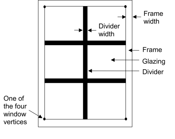
A window with frame and divider
- WindowProperty:AirflowControl - defines windows that have forced air flow between the panes of glass, also called heat-extract windows or climate windows. See the example file AirflowWindowsAndBetweenGlassBlinds.idf.
- WindowProperty:StormWindow - allows the definition of a movable storm window that is usually applied to a window in the winter. See the StormWindow.idf example file.
- InternalMass - used to define thermal mass that is not described anywhere else in the model - often used to capture the effect of furnishings or interior floors that are not being modeled. Used in many example files including RefBldgLargeOfficeNew2004_Chicago.idf.
- ShadingProperty:Reflectance - specifying the reflectance properties for shading and is only needed if the input object Building specifies the "with reflections" option. See the ReflectiveAdjacentBuilding.idf example file.
Other less common input objects include ZoneList and ZoneGroup that can be used when doing multi-story simulations and GeometryTransform which allows a building model to be stretched with just a few inputs.