Condenser Loop (Condenser Loop) - Cooling Tower
The Condenser Loop is constructed by using a PlantLoop object. It uses a cooling tower (modeled by using a CoolingTower:SingleSpeed object class) and a constant speed pump (modeled by using a Pump:ConstantSpeed) to supply cooling water to the electric chiller (modeled by using a Chiller:Electric object). Therefore, the supply side of the loop contains the Cooling Tower and the demand side contains the electric chiller. The loop is operated by using plant equipment operation schemes, and schedules. Refer to Figure 61 for a simple diagram of the Condenser Loop.
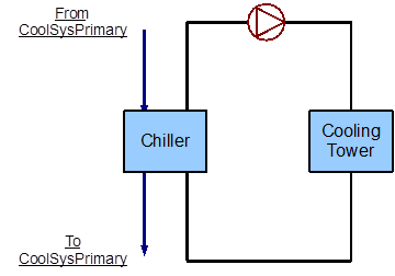
Figure 61: Simple line diagram for the condenser loop
Flowcharts for the Condenser Loop Input Process
This series of flowcharts serve as a guide for identifying and inputting the Condenser Loop and its components into the input file. The EnergyPlus line diagram for this loop is provided in Figure 62. A simple flowchart for the separation of the half loops is provided in Figure 63.
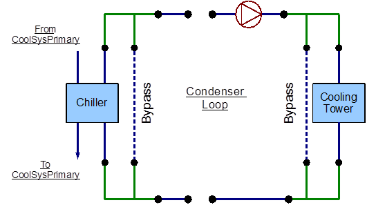
Figure 62: EnergyPlus line diagram for the condenser loop
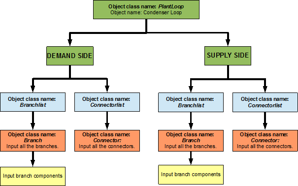
Figure 63: Simple flow chart for separation on half loops in the condenser loop
Condenser Loop Supply Side Construction
The main components on the supply side half loop for the Condenser Loop are the Cooling Tower that supplies the cooling water and the constant speed pump that circulates the cooling water through the loop. This half loop supplies cooling water to the electric chiller on the demand side half loop. The supply side half loop contains four components, four branches, eight nodes, and one splitter-mixer pair. The EnergyPlus line diagram for the Condenser loop supply side is provided in Figure 64. The flowchart for supply side branches and components is provided in Figure 65. The flowchart for supply side connectors is provided in Figure 66.
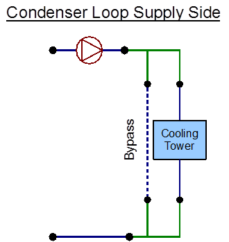
Figure 64: EnergyPlus line diagram for the supply side of the condenser loop
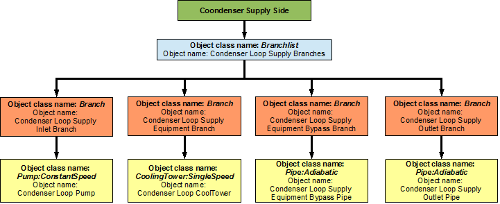
Figure 65: Flowchart for condenser loop supply side branches and components
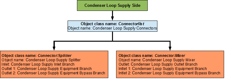
Figure 66: Flowchart for condenser loop supply side connectors
Condenser Loop Demand Side Construction
The main component on the demand side half loop is the Chiller that uses the cooling water supplied by the cooling tower. The chiller in turn is used to supply chilled water in the Primary Cooling loop. This side of the loop also has eight nodes, four components, four branches and one splitter-mixer pair. An EnergyPlus schematic for the demand side is provided in Figure 67. The flowchart for demand side branch definition is provided in Figure 68. The flowchart for the demand side connectors is provided in Figure 69.
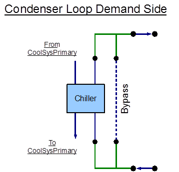
Figure 67: EnergyPlus line diagram for the demand side of the condenser loop
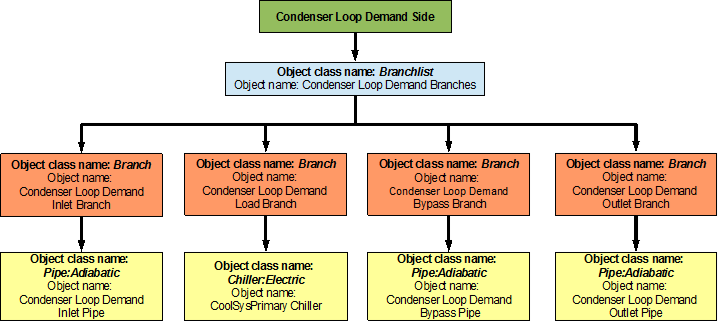
Figure 68: Flowchart for condenser loop demand side branches and components
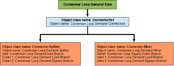
Figure 69: Flowchart for condenser loop demand side connectors
Flowcharts for Condenser Loop Controls
The Condenser Loop is operated by using set-points, plant equipment operation schemes and schedules.
Condenser Loop Schedules
The flowchart for condenser loop schedule definition is provided in Figure 70. The Condenser loop uses one schedule to operate properly. PlantOnSchedule is a compact schedule that keeps the Cooling Tower On at all times of the day, this compact schedule uses a discrete ScheduleTypeLimit (On/Off) which defines that the value of On is 1 and that of Off is 0.
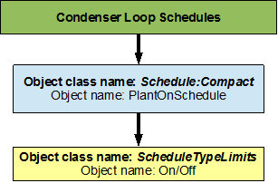
Figure 70: Flowchart for condenser loop schedules
Condenser Loop Plant Equipment Operation Schemes
The PlantEquipmentOperationschemes object uses the PlantOnSchedule and the Condenser Loop Operation Scheme objects to set the range of demand loads for which the cooling tower is operated during the simulation period. A flowchart detailing the Condenser Loop plant equipment operation schemes is provided in Figure 71.
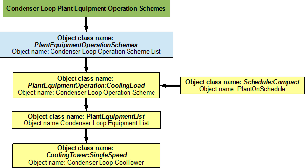
Figure 71: Flowchart for condenser loop plant equipment operation schemes
Condenser Loop Setpoints
The MyCondenserControl setpointmanager places a temperature setpoint at the Condenser Supply Outlet Node. The temperature at this point is controlled with respect to the outdoor air wet bulb temperature at that point in the simulation. The outdoor air wet bulb temperature is obtained from the weather data at the location of the simulation. The minimum setpoint temperature is 5 degrees Celsius and the maximum setpoint temperature is 80 degrees Celsius. A flowchart for Secondary Cooling loop setpoints is provided in Figure 72.
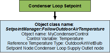
Figure 72: Flowchart for condenser loop setpoints
Condenser Loop Sizing
The Condenser loop is sized such a way that the design loop exit temperature is 29.4 degrees Celsius, and the loop design temperature difference is 5.6 degrees Celsius. A flowchart for the chilled water loop sizing is provided in Figure 73.
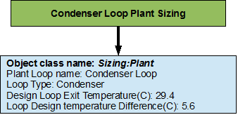
Figure 73: Flowchart for condenser loop sizing